On this page, you find some tips & tricks regarding using and programming the Raspberry Pi which resulted from my own experiences with the Pi. Please note that the content here just is a result from some "just for fun" activities with the Pi; nothing of what is shown here has been used in "production mode" so far. Furthermore, you will for example not find many comments etc. in the source code snippets I provide here on this page. Of course this is not really a good programming style, but nevertheless I am quite sure that the information which accompanies these source code snippets will make it possible to understand what has been coded there.
One important thing: I do not guarantee that anything shown here will work perfectly under every circumstances. For me, the things shown here worked, but one never know what happens if you adapt the source code snippets etc. for your own project. Also, please notice the disclaimer statement on the bottom of this page.
If there should be any questions or comments, you are welcome to contact me. You find the contact information (e.g. my email address and links to my business network profiles) on the main page of this domain.
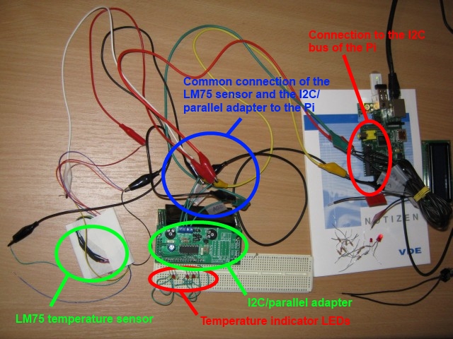
The idea for this "debug environment" mostly was to attach some LEDs directly to the output pins of the adapter, so that I could check if the pins were correctly set to "on" resp. to "off" if the corresponding command was send to the adapter. I don't think I need to say that the result of this debugging was that the adapter worked correctly, i.e. the pins had the correct values for each command. Nevertheless, the LCD display still refused to work, but at least I got another idea of what to do with this adapter, combined with the LEDs attached to it: it was a nearby idea to combine this with the LM75 temperature sensor which I attached to the Pi earlier, and to use the LEDs as a signal for the measured temperature. On the one end of the setup, there is the LM75 sensor, and on the other end of the setup, there is the I2C/parallel adapter, to which a number of LEDs is attached. Both of these hardware elements are attached to the I2C bus of the Pi, and on the Pi, there is a Java programm running, which on the one hand polls the current temperature from the LM75 sensor, evaluates the measured temperature, and on the other hand switches the different pins of the I2C/parallel adapter on or off depending on the measured value.
In the actual program, the first LED is switched on when the temperature reached 22 degrees celcius, and for every additional half degree more, an additional LED is switched on. If the measured temperature exceeds 25.5 degrees celsius, the LEDs are set to a flashing mode to depict that this upper threshold is reached.
With these low and tight temperature intervals, this can easily be demonstrated by simply touching the LM75 sensor in order to warm it up a little bit. This is shown on this video:
The following picture depicts the setup a little more in detail:
... and yes - of course I know that one cannot really use this as a clinical thermometer. But nevertheless, it was a nice gimmick, which was build in less than one hour... ;-)
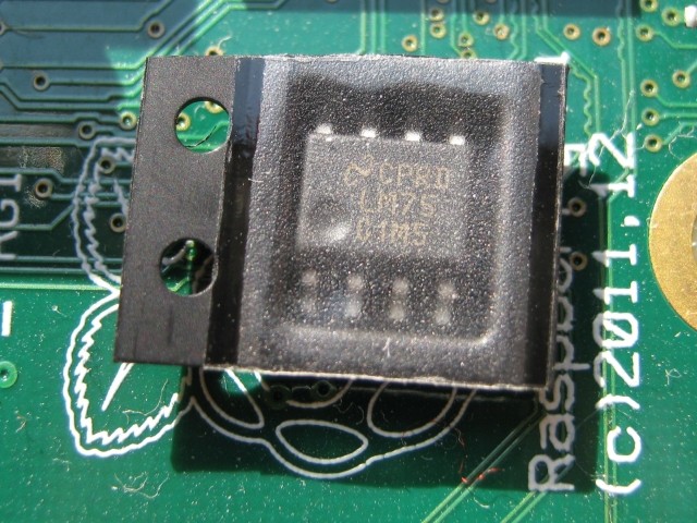
First of all, this is how the sensor looks like (still in its wrapping):
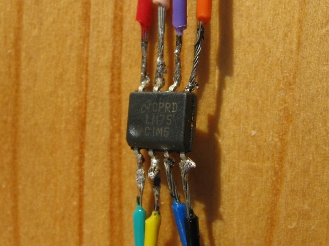
First of all, the pins of the sensor must be made somehow connectable to the Pi. Because I wanted to test this sensor as fast as possible, I did not create a circuit board to put this chip on, but I directly soldered some wires to its pins:
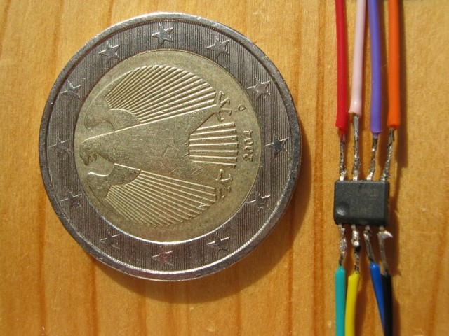
The following picture one more time depicts how small the chip (and so its pins) is by comparing it to a 2 Euro coin:
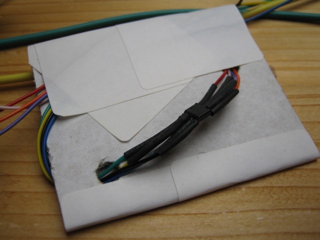
After the wires were soldered to the LM75, I used some heat shrink tube to protect the connections between the pins and the wires, and enforced the whole thing by mounting it on a simple piece of paperboard:
Now, the wires can easily be connected to the corresponding connectors of the Pi expansion header, which also provides a 5V power supply which can be used for the LM75. The following table depicts how the pins of the LM75 must be connected to the Pi:
| LM75 pin | Pi expansion header pin |
|---|---|
| SDA | GPIO 0 (SDA) |
| SCL | GPIO 1 (SCL) |
| Power supply | +5V power |
| Gnd | Ground |
| A0 | Ground |
| A1 | Ground |
| A2 | Ground |
| O.S. | (do not connect to the Pi) |
Now, everything is almost ready for a first test if the sensor is correctly connected - as long as you already have already installed the I2C driver and tools on your Pi. If you have not yet installed these, I recommend to take a look at http://www.skpang.co.uk/blog/archives/575, which worked quite well for me when I installed these.
Once these tools are installed, log on to the Pi, and type "i2cdetect -y 0" (note: there are 2 I2C buses available, so if you do not find the LM75 on bus 0, please also try bus 1: "i2cdetect -y 1"). If you connected the LM75 correctly, the result should look like the following:
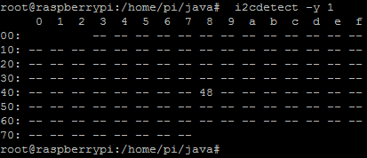
In this example, the LM75 is attached to bus 1, and has the address 0x48. So now, we are ready to go to the Java coding in order to use the data provided by the LM75!
In the following, I used the Pi4J library in order to interact with the I2C bus.
The following snippet depicts how to create access to the I2C device with the bus / address data mentioned above:
	private I2CDevice lm75 = null;
	private String busNumber = "1";
	private String deviceAddress = "0x48";

	public I2CDevice getI2CDevice() {
		if (this.lm75 != null) {
			return this.lm75;
		} else {
			try {
				I2CBus i2cBus = I2CFactory.getInstance(new Integer(busNumber)
						.intValue());
				this.lm75 = i2cBus.getDevice(Integer.decode(deviceAddress).intValue());
			} catch (IOException e) {
				e.printStackTrace();
			}
		}
		return this.lm75;
	}
So now, we have the method to get access to the Lm75 sensor! Great!
Now, we only need to retrieve the temperature data from the LM75, and to convert this raw data into actual celsius degrees. Because the LM75 uses 9 bits for the data, we have to read two bytes for each temperature data packet. This is depicted in the next snippet:
	public void someVoid() {

		// the next line retrieves an instance of the class which
		// provides the getI2CDevice() method depicted above
		final Lm75Lib lm75lib = Lm75Lib.getInstance();
		try {

			// just read the temperature for 3 minutes...
			for (int i = 0; i < 180; i++) {

				byte[] buffer = new byte[2];

				lm75lib.getI2CDevice().read(buffer, 0, 2);

				// this conversion will be depicted below!
				float currentTemp = Lm75Lib.convertBitsToCelsiusFloat(buffer);

				System.out.println("Temperature in celsius: " + currentTemp	+ "\n");

				Thread.sleep(1000);

			}
		} catch (IOException e) {
			e.printStackTrace();
		} catch (InterruptedException ire) {
			ire.printStackTrace();
		}

	}
Finally, only one thing is missing: the conversion of the two bytes read from the LM75 into degrees celsius. For the correct conversion, some knowledge about how this data is encoded by the LM75 is required: as mentioned, the LM75 uses 9 bits to store the data in. The first 8 bit contain the complete degrees encoded as complement on two, i.e. this covers all numbers from -128 to +127. For this, nothing needs to be converted; this value can be directly taken. The decimal unit of the temperature is measured only in half degrees by the LM75, and is encoded in the least significant bit of the 9 bit sequence. This means that this bit is the highest bit in the second byte read from the LM75; the other 7 bit of this byte are not set by the LM75, and must thus not be evaluated. If the highest bit in this byte is set to "1", this means that the decimal part of the temparature is used, i.e. the value "0.5" must be added to the complete degrees of the measurement. Because we read this bit as the highest bit of a byte value, we know that this is the case if this complete byte has a negative value. This leads to the last snippet, which depicts this conversion function:
	public static float convertBitsToCelsiusFloat(final byte[] bytes) {

		float retVal = 0f;

		if (bytes[1] >= 0) {
			// this is the case if the byte indicating the "0,5°C" part was set
			// to 0 = no 1/2 degree was measured.
			retVal = bytes[0];
		} else {
			// the very first bit of the "0,5°C-indicator byte" was set to "1",
			// so that this byte has a negative value --> a 1/2 degree was
			// measured.
			retVal = bytes[0];
			retVal = retVal + (0.5f);
		}
		return retVal;
	}
So finally, we are done! The LM75 sensor was successfully connected to the Pi, and we are able to read the data from this sensor, and to evaluate this data!
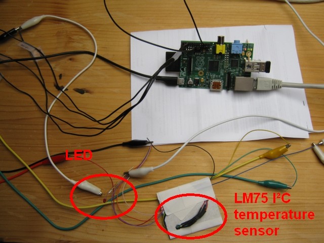
If we now combine this temperature measing with the LED control described later on this page, we can do the funny thing shown in the following video. The image on the right depicts the experimental set-up used in this video:
|
In this video, a Java program running on the Pi is used to evaluate the temperature data delievered by the LM75 sensor attached to the Pi. If the temperature reaches a defined threshold, the LED which is connected to one of the GPIO pins of the Pi is switched on (resp. switched off if the temperature falls under the threshold again). A simple lighter is used to heat up the LM75 sensor. Please note that there is always a delay of some seconds, because the sensor needs some time to warm up resp. cool down again.
After these commands have been executed, you can simply write into these file for example from inside a Java program (which afterwards must be JAR'ed and executed on the Pi):
	private static final String FILEPATH_PREFIX = "/sys/class/gpio/gpio";
	private static final String FILEPATH_SUFFIX = "/value";

	/**
	 * Writes into a GPIO PIN field.
	 *
	 * @param id
	 *            ID of the PIN (the number).
	 * @param content
	 *            Content to write. Must be either 0 or 1.
	 */
	private static void writeConfigFile(String id, String content) {

		File file = new File(FILEPATH_PREFIX + id + FILEPATH_SUFFIX);
		try {
			BufferedWriter writer = new BufferedWriter(new OutputStreamWriter(
					new FileOutputStream(file)));

			writer.write(content);
			writer.flush();
			writer.close();

		} catch (FileNotFoundException e) {
			e.printStackTrace();
		} catch (IOException e) {
			// TODO Auto-generated catch block
			e.printStackTrace();
		}

	}
If you performed the few easy steps as described above, you can access the GPIO PINs - for example to control some LEDs as shown in this video:
Disclaimer: Please note that the tips on this page come without any warranty. If you do not know what you are doing, think really good about trying it - it may damage or destroy your hardware and your software!